Table of Contents
The Meter properties are displayed, but because you set the mode to Define Custom, you can now make changes to this Meter without it impacting the Meter Effect inserted on the other busses.
The Input and Output meters are the most dominant display in the Effect Editor. The Input meters the actual signal, but the Output meter represents a value that can be sent as an RTPC. A note at the bottom indicates that this Meter will only be active if a Capture is active.
-
Click the Capture button, play the music, and then play a Stinger.
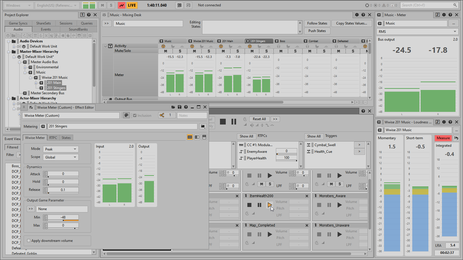
You see how the Output meter moves in a similar way to the Input meter; however, there is only one graph for the Output meter, compared to the stereo Input meter. This is because the output value is based on a sum of the channels on the Audio Bus.
Currently, the Output meter reacts instantly to changes in the source signal; however, like a Slew Rate, you can change the Output meter’s ballistics to respond differently, smoothing the response of the output signal. This will be useful when this value is used to affect the main music bus: the changes will be less abrupt.
-
Experiment with different Release values and end with a value of 0.5 seconds.

You may have noticed that the highest level on the Output meter range is different than the highest level on the Input meter range. The Output meter range is determined by the Output Game Parameter area’s Min and Max values. This allows you to scale the output range of values to a different set of values. In this case, you’ll change the Max range to 6, so there’s a one-to-one relationship between the busses actual meter level and the output value.
-
Set the Max Value to 6.
