|
Wwise SDK 2023.1.3
|
Introduction
The geometry passed to Wwise Spatial Audio may be used to simulate diffraction and transmission of sound. As such, it can completely replace your game engine's raycasting methods for computing obstruction.
When an emitter is hidden from a listener by an object, Spatial Audio computes paths along its edges and, if some are found, computes the diffraction coefficient resulting from the sound bending around these edges. The apparent angle of incidence of the emitter is modified accordingly, and the diffraction value is sent to Wwise where you may control how it ultimately affects the sound. Typically, diffraction results in low-pass filtering.
Additionally, Spatial Audio computes sound paths going through geometry. Sound transmitting though an obstacle has a transmission loss coefficient applied to it, resulting from the surface properties assigned to the geometry via the API. Typically, transmission loss is modeled with a low-pass filter and a volume attenuation.
The image below is a screenshot of the Game Object 3D Viewer in Wwise. It shows a sound with a diffraction path, diffracting around the edges of a thin wall, and a transmission path with a transmission loss of 100%.

 | Warning: Geometric diffraction and transmission can be used to entirely replace your game engine's raycasting method for computing obstruction, however the performance cost grows with the complexity of the geometry. Geometry passed to Spatial Audio should be kept as simple as possible. Also, it is good to use the efficient Rooms and Portals abstraction (see Rooms and Portals) in conjunction with Geometric Diffraction in order to reduce the computational complexity of the latter. |
Geometric diffraction can be used to affect the direct sound propagation path between the emitter and listener, but also the path of its early reflections, when used in conjunction with Reflect.
Setting Up Geometry for Diffraction
Each geometry set that is passed to Spatial Audio needs to say explicitly whether it should be considered for calculating diffraction paths. This is done via the AkGeometryParams::EnableDiffraction flag. This flag enables generation of edge data that is necessary for diffraction calculations, and is used for both geometric diffraction on the direct path and for diffraction of reflections.
Also, consider whether or not you want the boundary edges of a mesh to be able to diffract sound. For a given mesh, a boundary edge is defined as an edge that is connected to only one triangle and, therefore, exists on the boundary of the manifold. The complexity of the diffraction calculation increases with the number of edges, so the option should be disabled if your mesh contains boundary edges that should not diffract sound.
Finally, note that acoustic textures assigned to acoustic surfaces do not have any effect on diffraction because edge materials don't absorb energy. Edges simply bend sound.
Setting Up Geometry for Transmission
There are no additional steps required to set up geometry for sound transmission, however it may be desirable to adjust the transmission loss coefficient for various geometry types. For example, a concrete structure is likely to block almost all sound transmission, whereas geometry composed of plywood may block significantly less sound.
Each AkTriangle in the AkGeometryParams::Triangles array contains AkTriangle::surface, an index into the AkGeometryParams::Surfaces array. The AkAcousticSurface::transmissionLoss field describes how much transmission loss to apply to a sound transmitting though a triangle that references it. It is expressed as a value between 0 and 1. The transmission loss is converted to a percentage and then used to evaluate Wwise curves. The final volume attenuation and filter value applied to a sound with a given transmission loss will depend on the curves defined in the project. By default, the project occlusion curve is used. Custom transmission curves can be created in the Attenuation ShareSet added to the sound. Transmission loss may also be applied as a built-in parameter and can be mapped to an RTPC.
Geometric Diffraction of the Direct Path
Refer to the Geometric Diffraction demo and its code in the Integration Demo Sample (in SDK/samples/IntegrationDemo) for an example of using geometry for the purpose of geometric diffraction of the direct path. Look for Spatial Audio Demos > Geometry Demo.
Setting up a Sound for Diffraction and Transmission
In the Positioning tab in the Wwise Authoring tool, ensure that Enable Diffraction and Transmission is checked. This box enables Spatial Audio features related to diffraction and transmission, including:
- Computation of the diffracted path of the sound through geometry and/or portals, if applicable. The path calculation is performed by Spatial Audio on each game object that is currently playing a sound with diffraction and transmission enabled. If multiple diffraction-enabled sounds are playing on the same game object, the path calculation is only performed once.
- Computation of the transmission path of the sound, through geometry and/or between rooms. The final transmission loss coefficient is always taken as the largest transmission loss value encountered along the transmission path, whether it comes from a room's
AkRoomParams::transmissionLossor a triangle's associatedAkAcousticSurface::TransmissionLoss. - Generation of virtual positions for diffraction paths, which are sent to the Sound Engine for rendering the sound, assuming Spatial Audio's initialization setting
AkSpatialAudioInitSettings::bCalcEmitterVirtualPositionis set. - Application of curves according to the diffraction coefficient and the transmission loss coefficient.
By default, the project obstruction curves are used for diffraction and the project occlusion curves are used for transmission. If the game has also set an obstruction or occlusion value via AK::SoundEngine::SetObjectObstructionAndOcclusion, the values will be added.
Custom curves for diffraction and transmission can be created by adding an Attenuation ShareSet to the sound. Use the Attenuation Editor to create custom curves on Volume, LPF and HPF and fine-tune them while monitoring. For more information, refer to the Applying Attenuation section of the Wwise Help.
Direct Path Diffraction and Transmission in Wwise
Diffraction and transmission may be observed in the Game Object 3D Viewer, provided the proper profiling settings and view options are set (see the following images).
The calculated diffraction factor on a path from emitter to listener is displayed for each diffracting edge. Built-in Game Parameter values may be profiled by adding the bound Game Parameter to the Game Sync Monitor, and Obstruction and Diffraction may be profiled in the Profiler's Obs/Occ tab.
The calculated transmission loss factor is displayed beside the corresponding transmission path in the Game Object 3D Viewer. If the source of the transmission loss is from geometry, a hit point is indicated, with the accompanying transmission loss percentage. If the source of the transmission loss is from a room, the transmission loss percentage is displayed with the text "(Room)" appended below.


Like with Portals, the Diffraction value is 0 when the emitter is in direct sight of the listener, and it begins to increase as the emitter penetrates the shadow zone (see Diffraction). Also, please refer to Rooms and Portals' Diffraction for more details on shadow zone diffraction and for a discussion about using curves versus the Built-in Diffraction Game Parameter.
Direct Path Diffraction Interaction with Spatial Audio Rooms and Portals
With Spatial Audio Rooms and Portals (Rooms and Portals), Portals also model diffraction of direct sounds in adjacent rooms. The two systems complement each other in that no geometry-driven diffraction paths are searched for emitters that are not in the same room as the listener. Provided that Rooms and Portals are much more efficient to calculate than geometry, it is beneficial to use both systems together to reduce computational complexity.
Geometric Diffraction of Early Reflections
Refer to the Reflect Diffraction demo and its code in the Integration Demo Sample (in SDK/samples/IntegrationDemo) for an example of using geometry for the purpose of geometric diffraction of Early Reflections. Look for Spatial Audio Demos > Reflect Demo.
As was noted above, early reflections may diffract off of edges, and Spatial Audio supports modeling this phenomenon when emitters are routed to Reflect.
Prior to explaining how to do it, we need to define view zone diffraction.
Consider the figure below. The emitter is in direct sight of the listener, but the listener is not hit by specular reflections. It is thus in the view zone. As was said in Diffraction, diffraction occurs in the view zone as well. However, in Wwise Spatial Audio, neither the Rooms and Portals or Geometric Diffraction of direct path models consider diffraction in the view zone, as it is negligible compared to the actual direct path. However, for reflections, view zone diffraction has a dramatic impact. Without diffraction, early reflections are heard in the reflection zone only, where they are purely specular. As soon as the listener enters the view zone, reflections become silent. With diffraction enabled, the edge contributes to diffract the reflected wave. Thus, the listener perceives the reflection, albeit with additional filtering and attenuation as they go around and away from the reflection zone.
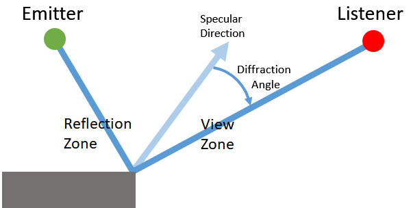
In the reflection zone, there is no diffracted path and, therefore, no diffraction value is calculated, because the specular reflection is assumed to take over. The calculated view zone diffraction of a given edge is 0% at the boundary between the reflection zone and the view zone, and 100% at the boundary between the view zone and the shadow zone.
With higher orders of early reflections, both view and shadow zone diffraction come into play.
Enable Reflections on Applicable Sounds
In the Wwise Authoring Tool, set the desired early reflections send to an aux bus containing Reflect for all sounds requiring reflections. Refer to Wwise project setup for more details. There is no specific setting needed to enable diffraction for the purpose of reflections' diffraction, apart from enabling diffraction on the geometry.
Settings in Reflect
Reflections that undergo diffraction effects will appear as image sources in Reflect. You may design the effect of diffraction on reflections with the three curves that depend on diffraction: Diffraction Attenuation, Diffraction LPF, and Diffraction HPF. See Reflect's documentation for more details.
Combining the Geometric APIs with Rooms and Portals
Rooms and portals in Wwise Spatial Audio work in conjunction with the geometric APIs for reflection and diffraction. The rooms and portals network can be thought of a high level abstraction (or as a low level-of-detail version) of the surrounding geometry. With care, the combination of rooms and portals with level geometry can result in a acoustic simulation that is both detailed and efficient.
Geometric Diffraction Through Portals
In the case where an emitter (assuming it is playing a sound that has been set up correctly for geometric diffraction, see Setting up a Sound for Diffraction and Transmission), is not in the same room as the listener, the geometric path is calculated as follows:
- The sound propagation paths from the emitter to the listener are calculated using the rooms and portals network.
- For each path, the segment of the path between the emitter and the portal closest to the emitter is calculated using the geometric diffraction algorithm, as if the portal were the listener. Unless the emitter is directly behind a single portal from the perspective of the listener, only one geometric path is calculated (the shortest one found). Calculating additional paths between the emitter and the portal would not result in unique virtual positions, and is therefore unnecessary.
- Path segments that are between two portals are also calculated using geometric diffraction if there is no direct line of sight between the portals. These calculations are done each time geometry and/or portals are added to or removed from the scene, and reused when required. In most cases, only the shortest path between the two portals is used. The exception being when the listener is directly behind one of the portals, in which case multiple paths are used to avoid discontinuities should the listener transition through the portal.
- For each path, the segment of the path between the listener and the portal closest to the listener is calculated using the geometric diffraction algorithm, as if the portal were the emitter.
- The resultant paths are taken as the combination of the above paths, branching and appending paths together where necessary.
Reflections Through Portals
Reflections can pass through portals and can reflect off of walls on either or both sides of the portal. Reflections can pass through more than one portal, possibly reflecting on surfaces between them if the reflection order is high enough (refer to AkSpatialAudioInitSettings::uMaxReflectionOrder). To ensure smooth reflections through portals, we recommend that you set AkSpatialAudioInitSettings::uDiffractionOnReflectionsOrder to at least 2, but be aware that increasing this setting also increases CPU usage.
Because the portal itself describes an acoustic opening, it is not necessary to also "cut holes" in the triangle geometry to allow a sound to pass through, which would greatly increase the number of triangles. A portal box represents negative space, so remember that any geometry that intersects a portal is effectively ignored, for example in a room where the geometry is described by a box, with two triangles for each of the six sides. To ensure that sound can propagate outside the box, add a portal that intersects one of the walls along the portal's z-axis.
| Warning: For reflections to be accurately calculated on each side of a portal, set AkGeometryInstanceParams::RoomID to an invalid AkRoomID. Unlike diffraction, reflection paths through portals are not calculated independently for each room and then later combined. Instead, reflections are calculated exactly as if the emitter and listener were in the same room, and the portal is treated as a hole in the geometry. |
Tips for Orienting Portals Between Rooms with Geometry
The following image shows an example of a correctly oriented portal.


|
|

|
|

|
|
Tagging Geometry for Specific Rooms (Diffraction Only).
| Warning: AkGeometryInstanceParams::RoomID is deprecated and the parameter will be removed in a future version. We recommend that you do not use RoomID, and instead leave it set to the default value (-1). |
As an optimization, assign AkGeometryInstanceParams::RoomID if all of the following conditions apply:
- Geometry is physically located in one room exclusively.
- Portals are used primarily for diffraction and sound propagation of reverb.
- Having accurate reflections pass through portals is not required.
- The Room referenced by
AkGeometryInstanceParams::RoomIDis not a Reverb Zone, nor is it a parent room of a Reverb Zone. In this case,AkGeometryInstanceParams::RoomIDis ignored. For more information about Reverb Zones, refer to Using Reverb Zones.
To limit the search space for ray-triangle intersection tests, you can manually assign geometry to specific rooms. To do so, set AkGeometryInstanceParams::RoomID to the ID of a particular room. This indicates to Spatial Audio that the Geometry Instance in that room is only visible from other rooms through portals and not directly. Because a single Geometry Instance can only be associated with one room ID, a room cannot have geometry that is visible in multiple rooms unless AkGeometryInstanceParams::RoomID is invalid. Also note that if any geometry set is associated with a particular room ID, then that room can no longer "see" geometry that is not explicitly associated with that room. After you assign a Geometry Instance to a room, Spatial Audio only looks for geometry that is specifically associated with that room ID when it simulates reflection and diffraction in that room.
Cette page a-t-elle été utile ?
Besoin d'aide ?
Des questions ? Des problèmes ? Besoin de plus d'informations ? Contactez-nous, nous pouvons vous aider !
Visitez notre page d'AideDécrivez-nous de votre projet. Nous sommes là pour vous aider.
Enregistrez votre projet et nous vous aiderons à démarrer sans aucune obligation !
Partir du bon pied avec Wwise