-
-
-
-
-
-
-
-
-
-
-
-
-
-
-
-
Glossary
-
-
-
-
-
-
(See the Wwise Flanger Properties below.)
Flanging is an audio effect that occurs when two identical signals are mixed together, but with one signal time-delayed by a small and gradually changing amount. This produces a swept comb filter effect: peaks and notches are produced in the resultant frequency spectrum, related to each other in a linear harmonic series. Varying the time delay with an LFO oscillator causes these to sweep up and down the frequency spectrum.
The Wwise flanger algorithm is based on a 'unified comb filter' that allows for controlling the depth of notches and peaks as well as their relative location (for example, on odd or even harmonics). This allows the comb filter to provide a wide variety of spectrum shaping by directly modifying the 'feedforward' and 'feedback' coefficients.
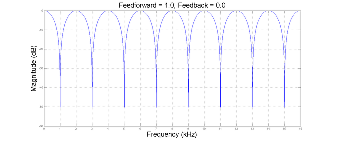

The following figures exemplify the type of magnitude response that can be achieved using a fixed delay time of 0.5 ms. The feedforward coefficient controls the depth of notches in the spectrum, while the feedback coefficient controls the magnitude of peaks.


The sign of the coefficient can control whether the notches or peaks occur on odd harmonics (for positive coefficients) or even harmonics (for negative coefficients) as shown below.


The feedfoward and feedback components can be used together to build different spectral shapes for combining the effect of notches and peak as shown below.

The delay time effectively controls the spacing between notches and/or peaks. By doubling the delay time, the distance between notches is halved as shown in the example below.
With the additional flexibility provided by the 'Blend' parameter which allows to mix the input to the delay line (including the feedback path) with the feedforward path of the delay line, effects other than flanging may be achieved.

One example of this is the vibrato effect (a regular pulsating change of pitch). Vibrato can be characterized by the amount of pitch variation and speed with which the pitch is varied. By setting both the feedback and blend values to 0, only the (modulated) feedforward path is preserved (vibrato component).
The Wwise Flanger plug-in contains a series of properties, many of which can be edited in real-time and can be mapped to specific Game Parameters using RTPCs.
|
Interface Element |
Description |
|||
|---|---|---|---|---|
|
Name |
The name of the Effect instance. Effect instances are a group of effect property settings. They can be one of two types: custom instances or ShareSets. Custom instances can be used by only one object, whereas ShareSets can be shared across several objects. |
|||
|
|
Displays the object's color. Clicking the icon opens the color selector.  Select a color to apply it to the object.
|
|||
|
Inclusion |
Determines whether the element is included or excluded. When selected, the element is included. When unselected, the element is not included. By default, this applies across all platforms. Use the Link indicator (to the left of the check box) to determine or to set platform-specific customizations. When this option is unselected, the property and behavior options in the editor become unavailable. Default value: true |
|||
  |
Indicates the number of elements in your project that contain direct references to the object. The icon is displayed in orange when references to the object exist, and in gray when no references exist. Selecting the button opens the Reference View with the object's name in the References to: field. |
|||
|
Notes |
Additional information about the Effect. |
|||
|
Metering |
Indicates the name of the object currently being metered. |
|||
 |
Allows you to browse for other objects to meter.
|
|||

|
Sets the display of the Effect Editor's selected tabs. By default, there is one panel displaying only one selected tab. You can, however, click a splitter button to split the panel into two, either side by side or one on top of the other, for two different tabs. The currently selected option is highlighted with a background color.
|
![[Note]](/images/2021.1.14_8108/?source=Help&id=note.png)
|
Delay |
The delay parameter used by the comb filter. Small delay values result in few spectral notches/peaks. Large delay values result in smaller spacing between frequency notches/peaks. Default value: 5 |
|||
Color Settings | ||||
|
Blend |
Scaling factor for signal not entering the modulated delay line (sum of feedback and dry signal). Can be used to create a large range of effect from flanging to vibrato. Default value: 1.0 |
|||
|
Feedforward |
Scaling factor for the contribution of the feedforward path out of the modulated comb filter. Large (absolute) values of this parameter results in stronger notches in the spectrum. Negative values places notches at even harmonic locations instead. Default value: 1 |
|||
|
Feedback |
Scaling factor for the contribution of the feedback path out of the modulated comb filter. Large (absolute) values of this parameter result in stronger peaks in the spectrum. Negative values place peaks at even harmonic locations instead. Default value: 0 |
|||
Output Settings | ||||
|
Wet/Dry Mix |
Controls the balance between the wet path (the output of the Effect) and the dry path (the input of the Effect). A value of 0 yields the original signal unaffected by the Effect while the a value of 100 outputs only the output of the Effect. Default value: 100 |
|||
|
Output Gain |
The amount of gain applied to the output signal after the dynamic compression that makes up for potential gain losses. Default value: 0 |
|||
|
Process Center |
Determines whether the Effect is processing the center channel or not. When unselected, the center channel is unaffected by the Effect. Default value: false |
|||
|
Process LFE |
Determines whether the Effect is processing the LFE channel or not. When unselected, the LFE channel is unaffected by the Effect. Default value: false |
|||
LFO Section | ||||
|
LFO Depth |
Amount of amplitude modulation that controls the actual delay length, in percentage. At 0%, the delay length used by the comb filter is always as specified by the delay parameter. At 100%, the delay length is modulated to its full range. Default value: 50 |
|||
|
LFO Frequency |
Frequency of the modulating signal. Default value: 1 |
|||
|
LFO Waveform |
Shape of the modulating signal. Values: Sine, Square, Triangle, Upward sawtooth, Downward sawtooth.
Default value: Sine |
|||
|
LFO Smoothing |
Amount of smoothing applied to the modulating signal. It is low-pass filtered by a certain value, mapped from 0 to 100%. At 0%, the signal comes out intact. With higher values, edges and discontinuities are smoothed.
Default value: 0 |
|||
|
PWM (Pulse Width Modulation) |
Applies to the square waveform only. Modulates the width of the pulse during one cycle. At 50%, the signal is at its full amplitude for half of the cycle, and is 0 for the other half. Near 100%, the signal is at its full amplitude for almost all the cycle, while it drops to 0 for a very short amount of time. Default value: 50 |
|||
Initial Phase Section | ||||
|
LFO Phase Offset |
Offsets phase of the modulating signal of all channels by a specific value.
Default value: 0 |
|||
|
LFO Spread Mode |
Defines how initial phase spread (see parameter “Spread”) is applied across channels. For example, with the spread mode set to “Front-Rear”, all front channels start playing with a phase equal to 0, and all rear channels start playing with a phase equal to “Spread”. If present (and processed), the LFE channel is always synchronized with the Front Left channel. Values:
Default value: Left-Right |
|||
|
LFO Phase Spread |
Amount of divergence in the initial phase spread across channels. The way in which this value affects each channel depends on the spread mode.
Default value: 0 |
|||
![[Warning]](/images/2021.1.14_8108/?source=Help&id=warning.png)
![[Caution]](/images/2021.1.14_8108/?source=Help&id=caution.png) |
Caution |
|---|---|
Keep in mind that the Feedback parameter can make the sound grow increasingly for large parameter values. |
|
Caution |
|---|---|
The effect tail (that is, the time after the input sound is finished during which the Effect continues to output data that it has accumulated in its delay line) does not consider feedback. This means that for strong feedback value the Effect could terminate with a significant volume still processed. |
See also Wwise Tremolo Properties for more detailed explanations on LFO parameters.
Was this page helpful?
Need Support?
Questions? Problems? Need more info? Contact us, and we can help!
Visit our Support pageTell us about your project. We're here to help.
Register your project and we'll help you get started with no strings attached!
Get started with Wwise