|
Wwise SDK 2023.1.3
|
The following sections explain how Spatial Audio affects signal flow in the voice and bus graph, and how it does so in relation to the sound propagation model.
Paths and Connections
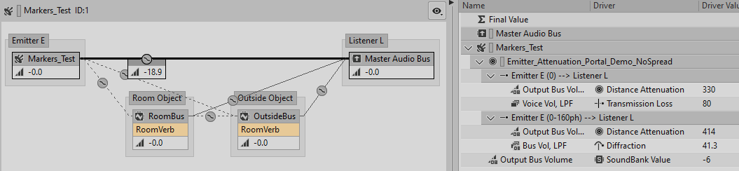
At runtime, voices and busses are connected to other busses, as can be seen in the Voice Graph or the Voice Inspector views of the Wwise Profiler. The "wires" between these Wwise Objects are referred to as Connections. An Emitter-Listener pair is created whenever a voice or bus associated to a game object (an Emitter or a Room) is connected to a different game object (another Room, or the top-level Listener). Emitter-Listener pairs, which we will refer to as paths for the rest of this discussion, are used to compute attenuation curves, amongst other things. There can be zero, one, or many paths within one connection. For example, when the game sets multiple positions to a game object using AK::SoundEngine::SetMultiplePositions, multiple paths are created. Spatial Audio uses paths extensively. In the following discussion, we will examine the paths within each connection in the simple scenario where an Emitter is located in a Room, adjacent to that of the Listener, as illustrated by the signal graph below.

Emitter-Listener (Direct) Connection
The connection between the Emitter and Listener carries the dry (unreverberated) signal between the Emitter and the Listener. Spatial Audio creates a first path between the position of the Emitter and the position of the Listener to represent the sound wave that travels directly from the Emitter to the Listener. Its length is thus the distance between the two, and the Emitter's attenuation curves are evaluated based on that distance. Also, unless the Emitter and Listener have a direct line of sight, an additional Transmission Loss factor is added to this path: it is the maximum Transmission Loss found on the geometry in a straight line between the Emitter and Listener (or the maximum of both Rooms' Transmission Loss if there is no geometry). We call this path the direct path, or the transmission path, depending on whether it has a zero or non-zero Transmission Loss.
It's often possible for another sound wave to reach the Listener by means of diffraction, either through a Portal, or around the edges of geometry. This is a diffraction path. It bends around an edge, and its total length is thus longer than that of the transmission path. It does not have Transmission Loss, but instead it has diffraction, proportional to the angles by which it bends.
The following image of the Voice Inspector shows two paths on the Direct Connection: one for transmission and one for diffraction through a Portal.
The following table describes the paths of the Direct Connection.
| Path Type (Number) | Characteristics |
|---|---|
| Transmission/Line-of-sight (1) |
|
| Diffraction (N) |
|
 | Note: No delay is applied to the diffraction paths, even though the wavefronts taking those paths travel a longer distance and should thus arrive at the Listener later than those taking the transmission path. |
All paths are contained within the same connection. They can be viewed as parallel sound propagation paths. Indeed, the signal of Markers_Test that is mixed into Master Audio Bus is panned and attenuated independently for each path. However, it is filtered by a single filter unit, whose cut-off frequency is based on the transmission-driven and diffraction-driven filter values of the various paths, and their respective prominence.
| Note: Technically, the existence of multiple paths in parallel should not violate the principle of energy conservation. Spatial Audio does not attempt to normalize the paths' volume in order to respect this principle. However, it utilizes the Multi-Direction panning method of the sound engine, which achieves a similar result in terms of volume normalization. |
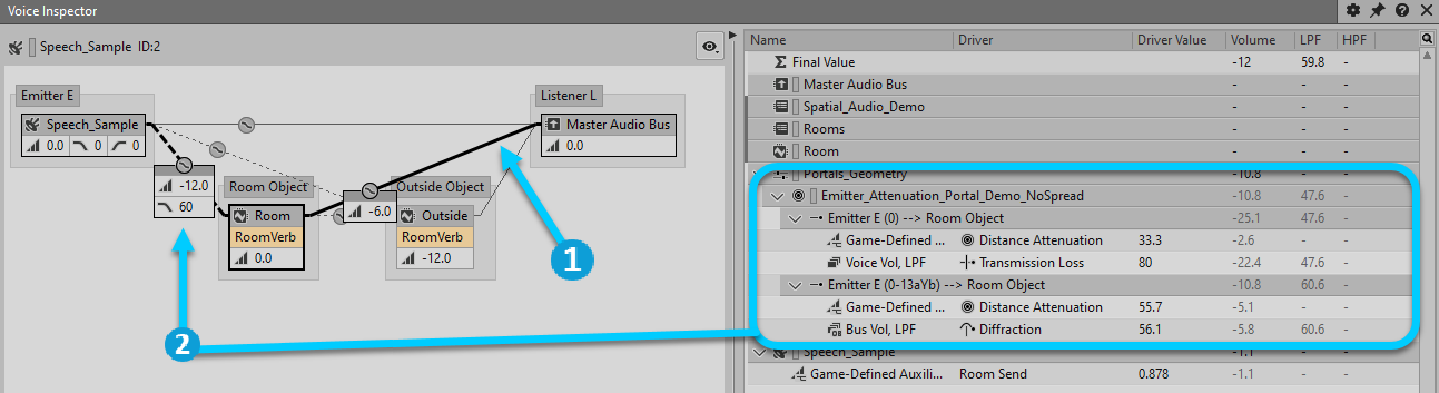
Emitter-Room Connection


| Emitter-Room connection |

| Room-Listener connection |
The auxiliary connection of the Emitter towards a Room bus represents the energy injected by the source that reverberates inside the Room and produces a diffuse field. There is a connection to the Room that the Emitter occupies, and additional connections to each of the Rooms adjacent to the Emitter. The adjacent Room connections, and their send levels, represent the proportion of acoustic energy that propagates through those Portals into the adjacent Rooms. The remaining proportion is sent to the Emitter's Room.
The connection to the Emitter's own Room contains paths that are comparable to the Direct Connection. The first path is a straight line to the Listener with distance attenuation, as well as Transmission Loss if there is no line of sight between the Emitter and Listener. There are also diffraction paths, which are longer than direct / transmission paths, and have diffraction instead of transmission.
The additional connections to adjacent Rooms work the same way, except that the Portal that connects the Emitter's Room to the adjacent Room can introduce diffraction on the direct/transmission path: If an adjacent Room is not part of the shortest path from the Emitter's Room back to the listener, then diffuse energy exits the Room and "loops back" on trajectories perpendicular to the Portals' opening. Diffraction angles are computed from Portals' normal vectors if they have to bend to reach the Listener. (See Wet Path Diffraction)
Room-Listener Connection
The connection between a Room's bus and the Listener represents the Room's diffuse energy, simulated by the reverb Effect, propagating to the Listener. Unlike the previously discussed connections, filtering is applied "upstream", per sound, on the Emitter-Room connection, therefore although this connection does embed paths, they are only used for spatialization and Spread.
| Note: Auxiliary busses used in Spatial Audio to represent Rooms normalize their outputs across the number of outgoing connections from each bus. A Room bus with two outgoing connections, for example, often reports -6 dB in the Voice Graph when you select either of those outgoing connections. This normalization is not otherwise reported in the Contribution List. |
| Note: The model does not take into account further obstruction due to geometry outside the Room. The effect of this geometry is assumed to be negligible. |
Distance-Based Attenuation of the Wet Signal
The length of the paths introduced in the previous sections, which represent the propagation of a Room's diffuse energy to the Listener, cannot be defined exactly. The model assumes that the attenuation of sound due to the distance traveled towards the walls and then from wall to wall is completely deferred to the reverb Effect itself. Thus, a reasonable approximation of a path's origin would be the middle of the Room. However, a more satisfying result is obtained if the distance attenuation of the Room's diffuse energy depends on whether the source that excited it is located closer or farther from the Listener, especially if the Room is large.
Furthermore, contrary to real-life physics, sounds in Wwise attenuate over distance using custom curves. In order to accurately compute the distance attenuation of the Room to the Listener, the Room should use the sound Emitter's attenuation curves. This poses a problem, because there can be multiple Emitters in a Room, each with its own position, and each with its own attenuation curve. Once all sounds within a Room have been downmixed and passed through a reverb Effect, it is impossible to selectively scale their volume based on their respective distance attenuation.
A brute-force solution to this problem would be to have a distinct bus and reverb effect for each sound within this Room. Since this would be prohibitively costly, Spatial Audio implements the following instead: The distance evaluation and attenuation, for the entirety of the distance between the Emitter and Listener, is applied on the connection between the Emitter and its immediate Room bus. That is, prior to the downmix and reverberation. This is mathematically equivalent to having one bus and reverb per source, as long as the Effects on the bus are linear. This is generally true with reverb Effects.
A similar principle applies to transmission and diffraction. In order for all parameters of a sound through Rooms to be customizable per-sound, those parameters are applied at the first connection between the Emitter and a Room. Every subsequent connection from Room to Room, or from a Room to the Listener are not filtered using these parameters. Assigning attenuation curves to a Room bus has no effect because they cannot be selectively applied to each sound in that Room.
Emitter-Room and Room-Listener Connections, Revisited
Attenuation, as well as Occlusion, Obstruction, Transmission Loss and Diffraction of the wet path is applied on the Emitter-Room connection, using the attenuation specified on the Emitter. Setting an attenuation on a Room bus will have no effect.
The following table describes the paths of the Emitter-Room Connection.
| Path Type (Number) | Characteristics |
|---|---|
| Transmission/Line-of-sight (1) |
|
| Diffraction (N) |
|
The following table describes the paths of the Room-Listener Connection.
| Path Type (Number) | Characteristics |
|---|---|
| Transmission/Line-of-sight (1) |
|
| Diffraction (N) |
|
The following image shows both connections in the Voice Inspector. The highlighted section shows the paths in the Emitter-Room connection, where distance attenuation, Transmission Loss, and diffraction are applied. Paths embedded in the Room-Listener connection are not displayed here.
|
| Room-Listener connection |
|
| Emitter-Room connection |
Coupling Between Rooms
The connection between the Emitter's Room and the Listener's Room represents the diffuse energy of the Emitter's Room transferred into the Listener's Room and contributing to its diffuse energy. This transfer occurs through walls and open Portals.
Like the Room-Listener connection, paths are embedded here only for spatialization. Transmission, diffraction, and distance attenuation have already been applied at the Emitter-Room connection (see the discussion in Distance-Based Attenuation of the Wet Signal).
| Note: If an open Portal exists, its propagation path will likely dominate the transmission path and enable coupling of both Rooms at full volume. The model does not try to modulate the transfer of energy based on the surface ratio of open Portals versus walls. This should be improved in a future release. |
| Note: The model assumes that geometry in the receiving Room does not interfere with the transfer of energy from the emitting Room. |
The following table describes the paths of the Emitter's Room to Listener's Room connection.
 | Tip: You can offset the volume of coupling connections by using the Game-defined aux send's Volume in the authoring tool. This volume applies to a given Room bus towards all connected Rooms. |
Connection Between Listener's Room and the Listener
This connection represents the diffuse energy of the Listener's Room that envelops the Listener. The distance attenuation has already been accounted for at the input of the connection, and therefore applies no additional attenuation. It is also assumed to be unobstructed, and its Spread is close to 100%.
Cette page a-t-elle été utile ?
Besoin d'aide ?
Des questions ? Des problèmes ? Besoin de plus d'informations ? Contactez-nous, nous pouvons vous aider !
Visitez notre page d'AideDécrivez-nous de votre projet. Nous sommes là pour vous aider.
Enregistrez votre projet et nous vous aiderons à démarrer sans aucune obligation !
Partir du bon pied avec Wwise