|
Wwise SDK 2023.1.3
|
Here is the outline of this page:
- Summary of Sound Propagation Features
- Modeling Sound Propagation from Other Rooms
- Diffraction
- Wet Path Diffraction
- Virtual Positioning and Diffraction Through Portals
- Transmission
- Room Coupling
- Multiple Room Traversal
- Room Game Object Behavior
- Room Tones
- Portal Spread and Aperture
Summary of Sound Propagation Features
The table below summarizes the features of Spatial Audio Rooms and Portals by grouping them in terms of acoustic phenomena, describing what Spatial Audio does for each, and how sound designers can incorporate them in their project.
| Acoustic Phenomenon | Spatial Audio | Sound Design in Wwise |
|---|---|---|
| Diffraction of direct path |
|
|
| Diffuse field (reverb) |
|
|
| Room coupling: reverb spatialization and diffraction of adjacent room's diffuse field |
|
|
| Transmission |
|
|
Modeling Sound Propagation from Other Rooms
With Spatial Audio Rooms and Portals, sound propagation in Rooms other than that of the listener is managed by the Rooms and Portals abstraction. An emitter in another Room reaches the listener via Portals, and their associated diffraction, and via transmission through rooms' "walls". Ensure that the Enable Diffraction and Transmission box is checked in the Positioning tab of each sound that need to be propagated.
Diffraction
For each emitter in adjacent Rooms, Spatial Audio computes a diffraction angle from the Shadow Boundary, from the closest edge of the connecting Portal. For more information, see Diffraction. This diffraction angle, which may go to up to 180 degrees, is then mapped to a coefficient between 0 and 100%, and given to the Wwise user for driving corresponding audio transformations, by one of two means. It can set the diffraction value on the emitter game object or set the value of the Diffraction built-in game parameter.
The diffraction value on the emitter game object is used to drive curves in the Authoring. By default, the project obstruction curves are used. They can be authored in the Project Settings' Obstruction/Occlusion tab and will impact Volume, LPF, and HPF to emulate volume and frequency-dependent behaviors. Project obstruction curves impact all the sounds in a project, which makes them less flexible. However, custom Diffraction curves can be created in an Attenuation ShareSet applied to the sound.
Alternatively, the Diffraction built-in parameter can be used. To do so, create a game parameter and set its Bind to Built-in Parameter drop-down menu to Diffraction. Values pushed to this game parameter are scoped by game object, so they are unique for each emitter. You may then use it with an RTPC to control any property of your Actor-Mixer. Output Bus Volume and LPF are privileged over the base Volume and LPF because they should apply to the direct signal path only, and not to the auxiliary send to the Room's reverb.
 | Warning: Compared to curves, using a built-in parameter requires more manipulations. Built-in game parameters also only apply on a single value for all positions of a game object. When multiple values are set, the smallest is taken. Recall that multiple game object positions are used when a Room has more than one Portal, so a built-in parameter is not recommended for this scenario. |
Wet Path Diffraction
A Room's diffuse energy is an essential part of the Wwise Spatial Audio sound propagation model. The reverb signal chain, or wet path, also has diffraction ("wet diffraction") applied to it. Wet diffraction models the diffuse field of a room being scattered as it propagates out of portals or around obstacles. Wet diffraction is applied on the input connection to the Room bus (that is, the auxiliary send from the emitter to the room), so that each sound uses its own individual diffraction curve. The wet diffraction value for each Room Auxilliary Send is calculated using the path between the emitter and the listener.
The wet diffraction calculation is similar to the dry diffraction calculation, but with a modified diffraction angle calculation as the path passes through the Room to which the emitter is sending. Spatial Audio assumes that the diffuse energy enters or exits a Room perpendicular to its Portals, and does not diffract inside the Room itself. Thus, when the path enters or exits the Room, it computes a diffraction angle relative to the Portal's normal vector, effectively using only half of the angle as the path bends into the Portal. All geometry inside the Room is ignored, because the Room is treated as an ideally diffuse field.
Consider the following scenario, with an emitter, listener, and a single sound propagation path. The emitter has two Room Auxilliary Sends: one to "Outside," the room the emitter is currently in, and one to "Room A," an adjacent room.
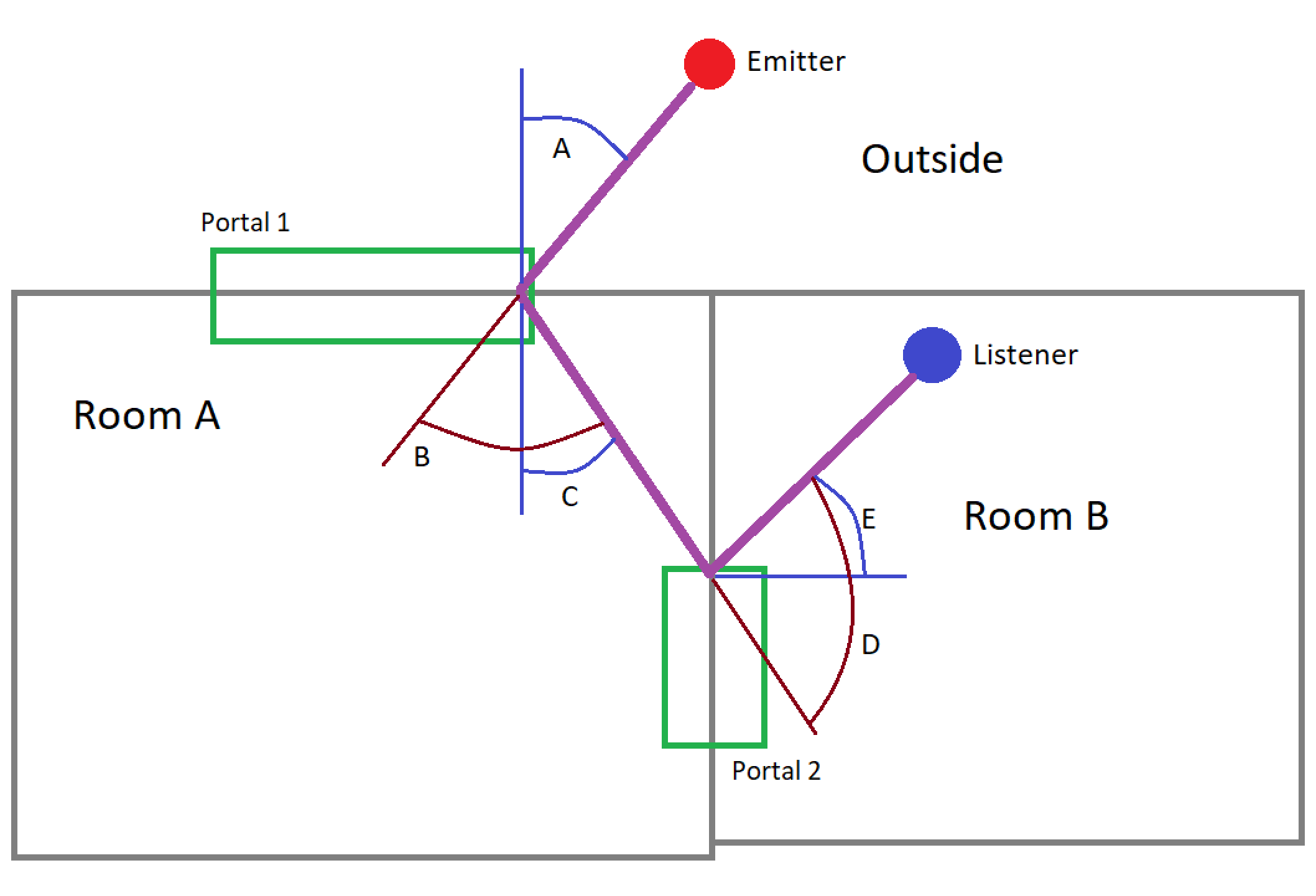
Wet diffraction is calculated separately for each of the two Room Auxilliary Sends:
- For the Room send to "Outside":
- There are no diffraction points (due to geometry) in the Outside Room, but if there were, they would be ignored, because the Outside is considered an ideally diffuse field.
- The path then exits Outside from "Portal 1." Diffraction from portal 1, as the paths exits the portal, is calculated using the portal normal. This is angle C.
- Portal 2 is not connected to Outside, so we use the standard diffraction calculation. This is angle D.
- TOTAL Wet Diffraction: C + D
- For the Room send to "Room A":
- There are no diffraction points (due to geometry) in the Outside Room, but if there were, they would be accounted for using the standard diffraction calculation.
- The path enters "Room A" through "Portal 1." Diffraction from portal 1, as the path enters the portal, is calculated using the portal normal. This is angle A.
- The path then exits "Room A" through "Portal 2." Diffraction from portal 2, as the paths exits the portal, is calculated using the portal normal. This is angle E.
- TOTAL Wet Diffraction: A + E
Finally, the wet diffraction value can never exceed the dry diffraction value. It is clamped if the calculation above results in a value greater than the dry diffraction value.
Virtual Positioning and Diffraction Through Portals
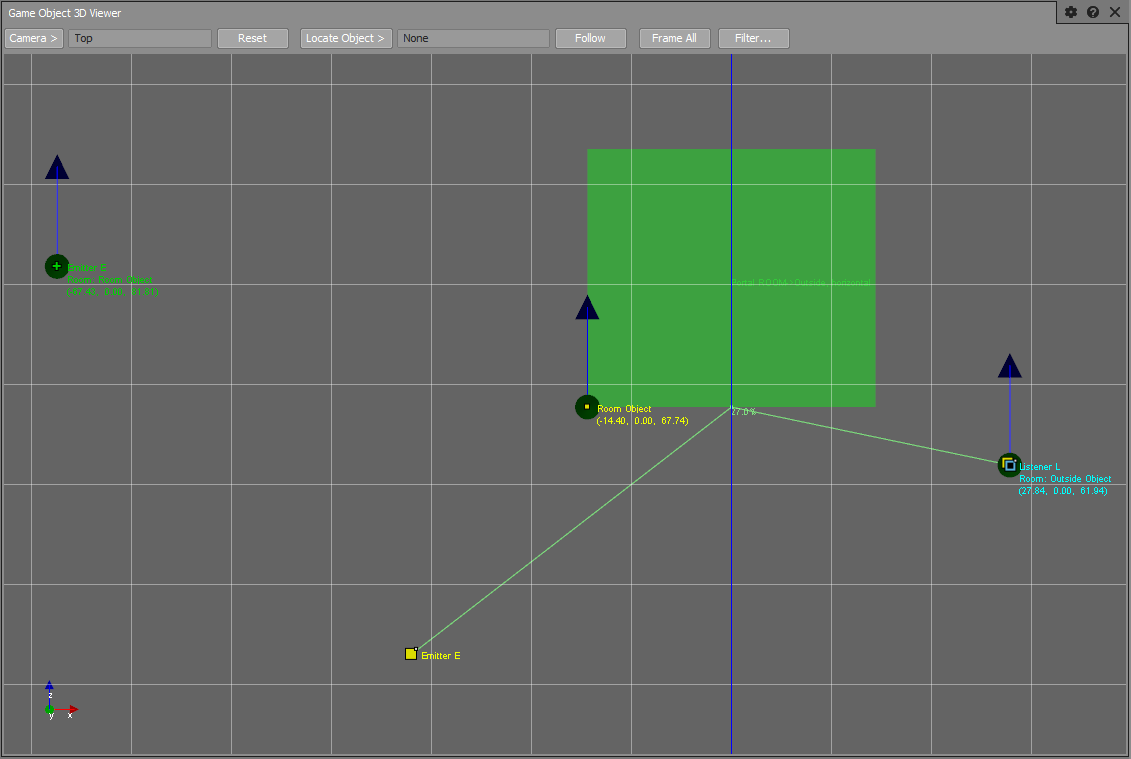
When the Spatial Audio's initialization setting AkSpatialAudioInitSettings::bCalcEmitterVirtualPosition is set, the position of the emitters located in Rooms that are adjacent to the listener is modified such that they seem to appear from the diffracted angle, if applicable. In the screenshot of the 3D Game Object Profiler, below, the listener (Listener L) is on the right of the Portal and the "real" emitter is on the lower left (Emitter E, without orientation vectors). Spatial Audio thus repositions the emitter to the upper left, so that the apparent position seems to come from the corner, all while respecting the traveled distance. The listener is about 45 degrees into the shadow zone of the Portal edge, resulting in a diffraction factor of 27%, as written at the junction between the two line segments.
When there are multiple Portals connecting two Room, Spatial Audio may assign multiple positions to an emitter (one per Portal). The MultiPosition_MultiDirection mode is used, so that enabling or disabling a Portal does not affect the perceived volume of other Portals.
Transmission
When an emitter is in a different room than the listener, and has no direct line of sight through a portal, Spatial Audio models sound transmission through walls by applying a transmission loss factor to the Game Object.
Spatial Audio models sound transmission between Rooms differently depending on whether or not geometry is available. Refer to Modeling Transmission Between Rooms with Geometry and Modeling Transmission Between Rooms without Geometry.
Regardless of how the transmission loss coefficient is derived, it is applied on the Room send connection, between the emitter and each Room, and is converted using the curves defined in the attenuation settings to map transmission loss to volume attenuation and filtering. Refer to Setting up a Sound for Diffraction and Transmission.
By default, the project occlusion curves are used for transmission. They can be authored in the Project Settings' Obstruction/Occlusion tab and will impact Volume, LPF, and HPF to emulate volume and frequency-dependent behaviors. Project occlusion curves impact all the sounds in a project, which makes them less flexible. However, custom Transmission curves can be created in an Attenuation ShareSet applied to the sound.
It is also possible to map transmission loss to any other Wwise parameter with an RTPC bound to the Transmission Loss built-in parameter. However it is difficult to use the Transmission Loss built-in parameter effectively because the transmission path is typically one of many sound paths between and emitter and listener, and RTPCs are applied at the Game Object scope.
 | Note: Using curves to simulate transmission loss is preferred over an RTPC, because it provides greater accuracy when modeling both transmission and diffraction. This is due to the fact that RTPCs can not be applied to individual sound paths, therefore any parameter mapped to a transmission loss RTPC will also affect any potential diffraction paths originating from an emitter. |
Modeling Transmission Between Rooms with Geometry
When geometry is available, sound transmission is modeled using AkAcousticSurface::TransmissionLoss. Spatial Audio Geometry allows for detailed sound transmission modeling because you can, if desired, assign different transmission loss coefficients to each individual triangle. Spatial Audio also uses room geometry to compute a spread value for the transmission path. When a sound emitter is blocked by one or more geometric surfaces, then the transmission loss factor of the geometry (as defined by AkAcousticSurface::transmissionLoss) is applied. If there is more than one surface between the emitter and listener, then the maximum transmission loss factor is taken. Refer to Setting Up Geometry for Transmission for more details.
| Note: For accurate room transmission, it is necessary to define a shape for the Room so that the Room has a source and an extent. The Room shape is calculated from the bounding box surrounding the geometry associated with the Room. To set up Room transmission via the API, refer to Setting up Room Geometry. If you do not want to use the geometry for diffraction and reflection calculation, set the AkGeometryInstanceParams::UseForReflectionAndDiffraction to false on the Room's AkGeometryInstance. |
Modeling Transmission Between Rooms without Geometry
If geometry is not available to Spatial Audio, the transmission loss value is approximated from each Room's AkRoomParams::transmissionLoss value. Transmission loss between rooms is calculated from the Room settings' AkRoomParams::TransmissionLoss parameter, by taking the maximum value between the listener's Room and the emitter's Room. A bounding box for the Room is approximated by fitting a bounding box around all Portals. This bounding box is used to calculate the spread value of the transmission path.
Transmission of Room Tones and a Room's Diffuse Field
In addition to sound transmission of individual emitters within a Room, Spatial Audio models sound transmission of the Room itself and this includes the contribution of the diffuse reverb field, as well as any Room tones that are playing inside a Room, transmitting through walls.
Transmission loss filtering and attenuation is applied at the input of a Room Auxilliary Bus, so that individual emitters can contribute differently to the reverb. However, it is the output of the Room Game Object that is spatialized. It is necessary to set AkRoomParams::transmissionLoss to properly spatialize the Room's reverb. A low transmission loss value emphasizes panning the Room towards the Room's center (the center of the Room bounding box) and a high value emphasizes panning towards the Room's Portals.
Because Room tones do not have a point source position, they also rely on AkRoomParams::transmissionLoss to simulate transmission. Therefore, it is always necessary to have a representative value assigned to the Room's AkRoomParams::transmissionLoss.
Room Coupling
The diffuse energy of adjacent rooms penetrating into the listener's room through Portals can be seen as sources located at these Portals and, as such, they should also contribute to exciting the listener's room. In other words, they should send to the Auxiliary Bus of the listener's Room. As written earlier, you can do this by checking the Enable Game-Defined Sends check box on the adjacent Room's auxiliary bus. You may tweak the amount that is sent to other rooms' reverb with the Game-Defined Send Offset.
Multiple Room Traversal
Sound propagation also works across multiple rooms. The Room tree is searched within SpatialAudio when looking for propagation paths. Circular connections are avoided by stopping the search when Rooms have already been visited. The search depth may be limited by Spatial Audio's initialization setting AkSpatialAudioInitSettings::uMaxSoundPropagationDepth (default is 8).
Room Game Object Behavior
Spatial Audio registers one game object to Wwise per Room, under the hood.
| Warning: This game object's position and aux send values should not be manipulated directly. |
When the listener is in a Room, the Room's game object is moved such that it follows the listener. Thus, the distance between the Room and the Listener object is approximately 0. However, its orientation is maintained to that which is specified in the Room settings (AkRoomParams). See Setting Up a Room Auxiliary Bus in Wwise for a discussion on the orientation of 3D busses.
When the listener is outside of a Room, that Room's game object adopts the position(s) of its Portal(s). More precisely, it is placed in the back of the Portals, at the location of the projection of the listener to the Portals' tangent, clamped to the Portals' extent. This can be verified by looking at the Room's game object, as seen in the screenshot of the 3D Game Object Profiler, above, in section Virtual Positioning and Diffraction Through Portals.
For multiple Portals, a Room's game object is assigned multiple positions, in MultiPosition_MultiDirection mode, for the same reason as with emitters.
When transitioning inside a Portal, the "in-Room" and "Portal" behaviors are interpolated smoothly.
Room Tones
The Room Game Object's primary purpose is to spatialize reverb (the emitter's "wet path"), however it is possible to leverage the spatialization behavior of Rooms and Portals (described in Room Game Object Behavior) and post events directly on the Room Game Object to implement room tones. For setting up room tones in Wwise, refer to Setting Up a Room Tone in Wwise. For posting events refer to Posting Events on Room Game Objects.
Portal Spread and Aperture
The spread of a sound in Wwise determines the width of the sound field that is constructed when a 3D sound is panned onto an Audio Bus. For most sounds, spread is defined in Wwise by a curve in the attenuation settings of the sound. However, for sounds played on Room Game Objects (i.e. room tones) and for the reverb sent to a Room Auxiliary bus, it is not necessary to define such a curve, because Spatial Audio calculates the spread automatically.
Furthermore, if a sound has a spread curve defined in the attenuation settings in Wwise, and that sound traverses one or more portals, its final spread value is subject to the Aperture value of those portals. The Aperture value can be thought of as an upper-limit placed on the spread of a sound, and simulates the constriction of the sound field as the sound passes through the portal.
The spread of a sound emitter can be visualized in the Game Object 3D Viewer in Wwise, with the following settings:
- Obstruction/Occlusion Data must be selected in the Profiler Settings dialog box prior to capturing data.
- Show Spread Cones must be selected in the Game Object 3D Viewer Settings dialog box.
The Game Object Spread and portal Aperture values can also be viewed in the Obs/Occ tab of the Advanced Profiler.
Game Object Spread
Game objects may have a Spread value that is calculated by Spatial Audio if they are Radial Emitters.
For Room Game Objects, the Spread value is the same as the Aperture value, and it is calculated by approximating the solid angle that each Portal subtends on the listener. Note that a Room Game Object has a unique spread value per Portal (each Portal is rendered as a unique sound position).
Portal Aperture
The Aperture value for a Game Object is calculated on a per-path basis, and is the result of the minimum spread value for all Portals traversed in a particular sound path. In the case of Room Game Objects, Spread and Aperture take on the same value.
Spread Calculation Summary
For a given sound position and listener pair, the final spread value is calculated as follows:
- The sound's spread curve is evaluated at the distance between the sound position and the listener.
- If no spread curve exists, the spread value is determined by the game object's radius (see
AK::SpatialAudio::SetGameObjectRadius). If no radius is given, and no spread curve is defined, the spread is take as 0%. - The sound's Aperture value is calculated from all Portals in the sound position's path. Multiple portals' Apertures are combined by taking the minimum value.
- The sound's spread (originating from the spread curve or the Game Object's Spread) and Aperture are combined by taking the lesser of the two. This is the final spread value passed to the panner in the Sound Engine.
Portal Area of Influence
The shape of a Portal is defined by the values in AkPortalParams::Extent. However, a Portal has an area of influence past the box formed by these extents. The effects of a Portal are based on distance from the Portal's center, up to AkPortalParams::Extent::halfDepth, and extend past the Portal's opening in every direction. Although the Game Object 3D Viewer displays a Portal as a rectangle, in practice this shape is rounded.
The following illustration is a top-down view of a Portal that connects a small Room to the outside.


| Room |

| Portal |

| Outside |
The area in green represents the Portal's AkPortalParams::Extent. The area in blue is the area of influence of the Portal while inside the small Room. The area in red shows the influence of the Portal while outside of the Room. This area extends around the corner and behind the Portal.
Was this page helpful?
Need Support?
Questions? Problems? Need more info? Contact us, and we can help!
Visit our Support pageTell us about your project. We're here to help.
Register your project and we'll help you get started with no strings attached!
Get started with Wwise